Myford

When, in September 1934, Cecil Moore founded the Myford Engineering Company and rented a spare room in a 5-storey lace mill in Beeston, Nottinghamshire (the address in the early sales sheets was given as Neville Works) few could have foreseen the day when, ten years later, he was to occupy all but a fraction of the same building and to continue trading, as the same company, until August, 2011. The foundation of this success - and the rise of Myford to pre-eminence amongst the then many competing makers of small lathes - was a range of just four machines: the very similar ML1, ML2, ML3 and ML4. Neat, compact and of appealing appearance all were designed and priced to appeal to the amateur market. However, despite their success, not even the most enthusiastic of owners could boast of them as state-of-the-art products and, by the close of the decade, the new-for-1937 American Atlas 6-inch (with its all-V-belt drive countershaft, roller-bearing headstock, fully-guarded changewheels and a host of user-friendly details) was setting the bench-mark for hobby-lathe design. In response, and designed during the closing years of WW2 (1939-1945) by Ted Barrs**, Myford launched what was to become the most popular and sought after small lathe in the UK, the ML7.

Undoubtedly drawing some design influence from American Atlas machines (including the 10-inch) the ML7 was announced to the press in February, 1946 with the first catalogue stamped "Provisional" and printed in the same A5 landscape format used for ML2 and ML4 publicity material; the cover was dark-blue with the single word "Myford" picked out in gold and in the company's traditional script. The pages were typed, reproduced on a Gestetner, and contained just one photograph showing the lathe mounted on its special "octagonal-form" braced sheet-steel cabinet stand. The first proper, fully illustrated catalogue was issued in October, 1947 and contained not only a complete technical specification but also cut-away diagrams and a list of the many and varied accessories.
From the start of production the ML7 was designed to accept a variety of profitable accessories (all listed and illustrated in the first full catalogue dated October, 1947) and very soon, with such an expandable and properly-engineered English small lathe on offer for the first time, many ex-service men (with gratuities burning a hole in their pocket) caused a lengthy waiting list to develop. The works prefix for the ML7 was "K" - with other contemporary designations including the ML.5 Capstan lathe being found as both the "F" and "R", the M.U. capstan as the "G", the M.L.6 capstan as "H" and the Myford/Drummond M-Type as "J". By the early 1950s, with just the ML7 in production (though a popular cylindrical grinder, the first of many, had also been introduced), it was decided that the market could stand the addition of a significantly altered and more highly developed lathe. Thus, in late 1952, the Super 7 was launched (with the provisional catalogue dated November of that year) - a machine that was able to accept all existing ML7 accessories.

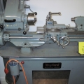
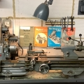
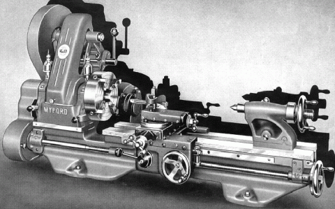
Myford ML7 3.5" x 20" gap bed, backgeared and screwcutting as it appeared in the late 1940s and early 1950s

Capacity

Both lathes can turn a maximum diameter of 7" over the bed and 10" by 1.5" thick in the gap; between centres the ML7 can handle material up to 20" in length and the Super 7 19" - or both a little more if you allow the tailstock to overhang the end of the bed. An ML7 is around 42" long and occupies a space about 22" front to back while a Super 7 is approximately 46" long and  a little deeper than the ML7 at around 27". Surprisingly,  a bench as little as 16" deep from the wall will accommodate an ML7. 
There were long-bed versions of both lathes: these admitted 31" between centres and were constructed with a very much deeper bed wall. Interestingly, the long-bed ML7 was fitted, as standard, with parts from the Super 7: apron, leadscrew, saddle and (slightly modified) cross and top slide units - although oddly, despite its appeal, this improved specification was never mentioned in contemporary catalogues. As an aside, although the cross slide on the long-bed ML7 (or at least some of them) appears to have been a standard Super 7 unit, its end bracket and the method of assembling the cross-feed screw to it were different (specification sheets for both ML7 and Super 7 are at the bottom of the page).

Of ribbed box-section, the bed was constructed with a flat top of typically English style, with narrow vertical shears, the nearer one in the gap between the front and back ways being shared by the saddle and tailstock. This was not an ideal situation but, in practice, caused no problems until the bed became badly worn when, as the tailstock was brought close to the headstock, it's central locating tennon became loose. With all the main surfaces at either the same level or at a right-angle to each other, one advantage of the bed design was the relative ease of regrinding with set-up times greatly reduced.  The back face of the bed was machined flat and equipped with tapped holes ready to accept a taper-turning attachment. The design of the saddle was interesting: shimmed plates were fitted  at front and rear by which means a very close vertical fit could be obtained; at the front, instead of a full length inner lip, just a short one was employed, no wider than the cross slide, and it was on this surface that tool thrust was taken. A consequence of this quirk is that the four gib-strip adjustment screws along the front edge of the saddle take some skill to set correctly with only two bearing against a firm surface; to get the setting correct the maker's instructions have to be followed to the letter. Towards the end of ML7 production, a New Zealand engineer pointed out that it would be better if the tool thrust was to taken along the full length of the saddle's inner rear face by using the bed's fourth vertical shear counted from the front. By this means an otherwise unused already-machined surface could be used and (combined with an adjustable gib strip) a much longer and more stable contact obtained. Unfortunately the New Zealander's proposed method, while possible in an experimental situation, was not suited for production and so Myford - probably following the appearance of an article in Model Engineer Magazine proposing a similar but rather more straightforward modification - came up with a system (from K107657) that involved machining away the original short contact lip at the front and using a modified casting to keep the relative position of apron and leadscrew the same. By this means the saddle to bed contact was arranged against the rear shear, yet the gib strip adjustment kept at the front.

Apron

Pressure die-cast in a form of ZAMAK (it looks like aluminium), the apron was fastened to the saddle with 3 cap-head screws and with the leadscrew clasp nuts guided in adjustable, gibbed ways. On early machines the reduction gearing between carriage traverse handwheel and rack was exposed (and quickly collect swarf and dirt) but this fault was soon corrected and a close-fitting cover provided. 

Cross and Top Slides

While the Super 7 was fitted from the start of production with a long slide as standard that on the ML7 was always shorter (with 5-inches of travel and four 3/8" T-slots) but with the option, at extra cost, of a longer 10.75-inch slide (and matching longer feed screw) with five T-slots. Even so, the standard slide had a generous 30 square inches of clamping surface and, with the top slide removed, was ready to be used as miniature boring table or to mount a milling slide or rear toolpost. Until Machine K108718, slotted BA screws and locknuts were used for the gib-strip adjustment but were then replaced by easier-to-set self-locking 5-mm pitch hexagon-socket screws .
Able to be swivelled 63-degrees either side of zero, the 2.5-inch travel top slide was fitted with the same 10 t.p.i. Acme-form feed screws as the cross slide and both carried identical micrometer dials die-cast in ZAMAK; these, while a "character" part of the machine, are not as easy to read as the properly-engraved units fitted to very late models. The toolpost clamp post was surrounded by three little tapped holes, intended to accept the mounting screws for the indexing plate used on the 4-way toolpost; as supplied from the factory each hole was sealed with a small grub screw to prevent swarf working its way through to the feed screw and wearing it out.

Headstock

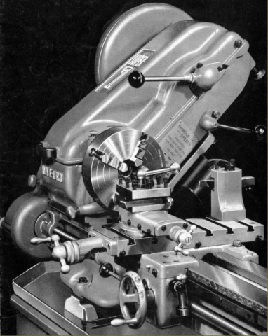
In comparison with almost every other contemporary small (British) lathe the headstock of the ML7 was a rugged affair. Bolted to the bed by four high-tensile cap-head Allen screws it was aligned by a ground rectangular locating tongue fitted into the gap between the bed ways with two pusher screws, entering from the rear, pressing against the tongue and so holding the headstock hard against the inner vertical bed way. The spindle was in 40-50 tons high-tensile steel and ran in plain, parallel Glacier TI Alloy "half-step" bearings with laminated (0.002") shims between the upper and lower halves to allow a reasonable fine clearance adjustment. Strong bearing caps were used, each bolted down by two socked-headed cap screws and with a ball-thrust bearing fitted in a shielded position at the left-hand end. The spindle was offset from the bed centre line towards the rear - a feature the makers ingeniously claimed in their first publicity sheet: "The distinct advantage of the offset is paramount when turning large diameters, the degree of rigidity being equal to that of a bed 5-inches wide with the headstock centrally disposed." The spindle on early machines was fitted with a pair of simple little No. 2 size wick oilers (easily neglected) while later models had proper drip-feed lubricators where the supply of oil could be adjusted (according to the spindle speed) and the quantity remaining easily inspected. The dimensions of the original spindle - 1.125" diameter, bored through 19/32", No. 2 Morse taper, front bearing section 1.25" diameter, rear bearing section 1", bull gear section 1.125", 12-threads-per-inch nose (the threaded section being about 0.62" long) backed by a plain register 1.25" in diameter and 0.4375" long - were carried over to the Super 7 and only changed with the advent of the new-for-2001 Super 7 Plus. The drive from countershaft to spindle was by a 3-step aluminium pulleys with a proper, full-sized A-section V belt that allowed full use to be made of the motor's power (generally 0.33 h.p. on early lathes and 0.5 h.p. on later). The robust backgear assembly (clustered at the front under the spindle line) meant that speeds down to around 25 rpm could be achieved with greatly increased torque - and no risk of belt slippage - ideal for both screwcutting and turning large blocks of metal held in a four jaw chuck, or on a faceplate. On both ML7 and Super 7 that part of the (bronze) backgear carried on the headstock spindle was in the form of a "sleeve pinion" - that is, the small gear was extended to form a long bush on which the pulley was pressed, the whole assembly rotating on the spindle when backgear is engaged - a design that did much to enhance the lathe's ability to run reliably at slow speeds for long periods. Unfortunately the assembly did contain a weak point: the three-step aluminium pulley was only pressed onto the sleeve - and it is not unknown for it to become loose and rotate. However, if the assembly is stripped, cleaned and the pulley secured onto the sleeve with a smear of low-strength Loctite, all will be well.

Changewheels and Screwcutting

Myford Series 7 10 changewheels of all years are 20 D.P. with a 14.5-degree pressure angle, 3/8" thick (0.375") with a 5/8" bore (0.625") and 1/8" keyway (0.125"). Supplied as standard with an ML7 or Super 7, the changewheel set comprised: 2 x 20, 25, 30, 35, 38, 40, 45, 50, 55, 60, 65, 70 and 75t. To cut a wide range of metric threads required, in addition, just two 21t wheels. 
In place of the crude assembly used in pre-war years, with plain-bore changewheels running directly on studs and retained by split-pins and washers, the changewheel drive on the ML7 was properly engineered. Hardened steel pins were employed, carrying bushes keyed into the gears and with neat, quick-release washers retained by slot-head screws allowing the gears to be changed quickly. Unfortunately, the nuts holding the studs were still behind the banjo, making any alteration in position a fiddly, time-consuming business (on the Super 7 the nuts were moved to the front, and the design of pin assembly improved with the use of a bronze bush). The changewheels, like the belts, were enclosed inside a neat, thin-walled cast-aluminium cover. Tumble reverse was fitted as standard, allowing quick reversal of the saddle drive - and so speeding up the boring of deep holes, etc. Setting the tumble-reverse lever to "neutral" meant that high speeds could be used without having to drive the changewheel set - and this made an already very-quiet lathe even more acceptable in a domestic situation - many being used in attics and even spare bedrooms. The 8 t.p.i. left-hand thread leadscrew was of Acme form, 5/8-inch diameter and ran in Oilite bushes. On the original ML7 both the tumble-reverse and backgear levers were tipped with lovely little acorn-shaped plastic knobs - in what must have been a subtle reference to Nottinghamshire's woodland heritage. For details of the screwcutting gearbox fitted to the Series 7 Myford lathes, see the section below about the Super 7

Tailstock

Able to be off-set on its sole plate for taper turning the tailstock was fitted with a 1-inch diameter barrel, threaded 8 t.p.i. and with a No. 2 Morse taper - so allowing heavy-duty drilling. The barrel was bored clear and passed through the handwheel - an arrangement that did have some advantages, notably if used for long-hole boring when woodturning. Arranged so that it sat underneath the barrel - and so passed though the greatest mass of material - the tailstock spindle lock was of the proper (and powerful) split-barrel type. A further advantage of this location was that it removed the need to incorporate a boss on the back of the tailstock body to hold the locking mechanism, though there was a slight inconvenience in having to reach over to grip the lever.

Improvements

Although the ML7 changed very little during its production life some improvements were made: the early machines had no oil nipple on the headstock pulley (essential to lubricate the long bronze bush that was formed as part of the backgear) but this is easily retro-fitted; by 1950 the countershaft had been given more substantial uprights and the back made solid instead of having three open panels: the original ball-spring "Bennet" oilers were replaced by proper nipples to which a pressure oil gun could be applied to blast out dirt and drive oil to where it would do some good (note: all nipples, on all models of the Myford 7 Series, took oil, never grease): by 1960 the tailstock casting was filled in and its "off-set" guide moved to a thicker part of the casting: in 1969, from machine K90494, a cast lug was added to the headstock to provide a location point for the lever-action collet closer - this had previously been supported by a loose bronze bracket, clamped by two Allen screws to one of the cast-in strengthening ribs behind and immediately below the front headstock bearing. 
During 1973, from machine K111727, production was rationalised around just one 7-Series bed, that for the newly-introduced, power-cross-feed Super 7, this being easily identified by a much deeper recess along the front face, a feature necessary to allow the much deeper power-feed apron to fit (there is a possibility that these beds were stamped with a serial number having a suffix "C". The change of bed also allowed the use of the Super 7 cast-iron apron and 3/4" diameter leadscrew (the Super 7 leadscrew nut clasp-nut handle is another recognition point). All these improvements that mean late versions ML7s  have the very best specification of all. The last ML7 manufcatured (K140848) left the assembly line on the 31st of January, 1979. 

ML7: Speed Range

As supplied to the UK market (with a 50 Hz 1425 r.p.m motor) the ML7 had a speed range of: 35, 62 and 110 in the 5.78 : 1 ratio backgear and 200, 357 and 640 rpm in open drive. Although it is perfectly possible to raise the top speed by increasing the size of the motor pulley, it is wise to bear in mind that the maximum recommended speed of the original white-metal bearing spindle is 1000 r.p.m. The writer has known machines to be run at much higher speeds, without apparent ill effect, but these were in good condition, carefully set up and with an increased flow of top-quality lubricant from their oilers; a worn machine treated like this might not take at all kindly to the treatment.
At one time, in order to permit higher speeds to be reached reliably, the option of a kit containing bronze headstock bearings and a hardened spindle was available - though at a cost well above that for the standard items. However, in later years, replacements were always provided as bronze-bearings (because the oil feed to the bearings is "constant loss", it is important to make sure that, every time the machine is run, both oilers are topped up and opened to give a generous rate of feed - one drop per 30 seconds as a minimum). I have seen countless ML7 lathes that, despite having given more than sixty years of service, still had bearings that were "spot on". Of course, the oil has to go somewhere and runs down the front and rear faces of the headstock to end up in the chip tray. If your headstock appears to be leaking oil, don't worry. However, if it's not, do worry…...it's run out.

Electric Motors

For quiet and smooth running the makers recommend a resilient-mounted motor (with rubber rings isolating the main housing from the foot) and, so equipped, an ML7 will turn almost silently. While all Super 7s had a clutch fitted as standard, on the ML7 this was an optional extra - but one well worth having. The ML7 unit economised by utilising the brake shoes from the front wheel of a Nottingham-made Raleigh moped, the "Gadabout".
Unfortunately one-phase motors are not the most reliable of devices. They are best run near their rated capacity all the time (i.e. worked nearly flat out); if such a motor is switched on and off frequently against "no load" the windings will be damaged and, if run through a cycle where it is started, worked briefly, stopped and started again, the capacitor will fail prematurely. 
It is very important not to "over-motor" a Myford (or indeed any other lathe); any accident or dig in will have far more serious consequences - and if the machine is worked beyond its capacity, excessive wear will occur. Early ML7s were fitted with 1/3 hp motors, later ones with 1/2 hp - the latter a figure that should not be exceeded. Apart from the very first examples, the Super 7 has always been equipped with a 0.75 hp motor (necessary to pull the top speed of over 2000 rpm) and this too should be respected as an absolute maximum. The original Brook-Crompton motors are very expensive; however, direct replacements, of exactly the same specification but more economically priced, are now available.

Buying a Used 7-Series - and value for money

When contemplating a used Series 7 Myford its age is irrelevant (unless you require a particular specification); mechanical condition is everything and I have seen many machines over 60-years old that have either had so little use, or been so carefully taken care of, that they appear to be virtually "as-new". While late machines had their serial numbers stamped into the front of the bed, just to the right of the gap, earlier versions in a difficult-to-find location punched into the vertical way on the rear of the bed at its tailstock end. If you can find a good-condition ML7, especially one with the original bed machining marks intact and wearing its maker's paint, it will represent tremendous value for money. In addition, even if the machine shows signs of careless use, most mechanical spares are available direct from the factory (or their successors) to restore it to "as-new" condition. With the removal from the spares-counter of the teenage girl, it was even possible (when the long-serving works manager Malcolm Townsend was in charge) to talk to somebody who knew the lathe intimately. Don't be tempted to make or modify parts yourself - use original components and preserve the authentic look and feel of the machine - this will not only enhance its value, but also make using it a much more secure and enjoyable activity. Many enthusiast have found that buying a well-worn machine and restoring it to useable condition is a fascinating exercise that demands the application of numerous skills to produce a useful (and valuable) end product.
It is much more difficult to find a good Super 7; competition for them is strong, which raises prices well above those of the ML7 - often twice as much, model for model; the ML7 really is the bargain version. 
A selection of used Myford lathes can often be found for sale here and photographs of a superbly restored ML7 here

Early version of the Myford Super 7

Super 7: General Specification and comparison with the ML7

When it appeared in late 1952 it was immediately obvious that the Super 7, although built with the same bed-way dimensions as the ML7, was a thoroughly re-engineered design, with many significant improvements. Super 7s of all years were well finished, but post 1960 models appear to have enjoyed more careful filling of the castings and a better cosmetic paint finish--as well as the traditional fully-machined and chemically-blacked nuts and bolts. As a way of instantly recognising the era of a Super 7, until 1959 the lathe had a distinctive drip-feed oiler built into the front of the headstock casting, the circular window of which was just to the left of the chuck. On these models the countershaft assembly ran on full-complement needle roller bearings with the (standard-fit) clutch contained within the countershaft's central 4-step cast-iron pulley. Surprisingly, the needle roller bearings gave rise to noise and vibrations, a problem was especially obvious when a quiet-running 3-phase motor is fitted. As the noise and vibration is caused by the scuffing of the rollers, a solution to the problem is to replace the originals with the caged equivalent. The clutch too was also prone to rattle unless correctly adjusted - reference to the maker's instructions on this point is vital.

Drive System

Powered by a 0.75 hp, 1425 r.p.m. motor and with a clutch fitted as standard the headstock drive system had 16 speeds. However, allowing for the fact that the two fastest backgear speeds in high range were not recommend for use, this gave 14 speeds of: 27, 39, 54, 77, 95, 135, 210, 300, 420, 600, 740, 1050,1480 and 2105 rpm - an especially 'deep' range that went a long way towards making the Super 7 such a versatile and adaptable machine. In the USA, with 60 Hz motors running at 1700 rpm, the speed range was correspondingly faster. The drive from the motor to countershaft was arranged with a two-step pulley (rather than the single of the ML7) - while the headstock spindle carried four speeds instead of three. Both countershaft pulleys, and the headstock cone pulley, were in cast iron (a much more suitable material than aluminium) and the rotating masses of which assist a single-phase motor by providing a small but useful "flywheel" effect. For many years the rather fragile and easily distorted two-step motor pulley was in aluminium, but this was changed to cast iron (so matching its countershaft equivalent) at some point in the 1980s. In June 1958, from lathe SK 8128, the clutch was incorporated in the large 2-step countershaft pulley and the countershaft bearings changed to plain Oilite bushes. This significant re-engineering of the drive (which also involved new belt-guard covers) made a huge difference to the running of the lathe making it both smoother and quieter. 
Headstock Bearings and Backgear

In place of the ML7's plain white-metal bearings the Super 7 spindle ran in a tapered bronze bush at the chuck end and a pair of angular-contact ball bearings at the rear. The ball-races were housed between screwed rings - which were used, by moving the spindle backwards and forwards, as a precision method of adjusting the front-bearing clearance. The spindle was immensely rigid and known for long, trouble-free life; the backgear assembly was similarly beefed-up, used stronger gears and was fitted with a very handy "flick-over" quick-release mechanism. In May 1959, from machine No. SK 9167, the expensive-to-produce drip-feed from bearing oiler was abandoned and a sump provided beneath the bearing with feed by a wick - a change that did at least have the advantage that it was no longer possible for foreign matter to find its way into the bearing. It is useful, though not official, to refer to these plain-bearing countershaft machines as the Super 7 Mk. 2. 
Tailstock

With a longer travel than the ML7, the Super 7 tailstock was also fitted with a ball-bearing thrust race, a quick-feed, multi-start thread, self-eject for the centres and a longer barrel and housing. Instead of the operating lever for the barrel lock being behind the unit--as on the ML7--on the Super 7 it was placed to face upwards, using a boss on the back of the casting to incorporate the mechanism. Fortunately this assembly was well built and, unlike that on the contemporary Boxford, not prone to failure under clumsy handling. On both lathes the tailstock can be improved immeasurably by the use of the optional lever-operated attachment; the increased sensitivity when drilling, especially on very small diameters, is well worth the expense.

Saddle and Apron

One unusual aspect of the lathe's design (shared with the ML7) was the arrangement of the saddle; although this had equal-length wings at front and back, at the front (where the thrust was taken out on the inside vertical way) only half the length bore against the bed.
However, from August 1972 and Serial No. SK 108891B, the thrust was changed to bear against the full length of the saddle at the rear - the alteration being brought about by correspondence with an Australian engineer who had conducted the necessary practical experiments. This change also helped to ensure the success of the power cross-feed mechanism introduced in March 1974, from Serial No. SK 115830.
Made from cast iron instead of "aluminium" as on the ML7, the Super 7 apron was more robustly constructed--though two minor changes occurred shortly after production of the power cross-feed started with the substitution, in June 1975, of the original bronze cross slide feed by one made from hardened steel (from lathe SK 122657) and in December 1975, (from SK 126004), with the power cross-slide feedscrew modified resulting in a larger counter-bore in its micrometer dial. Even today any type of power-cross-feed Super 7 is relatively rare on the used market, especially one owner, carefully-used examples. It would seem that, once you have one of these fine machines, you simply don't want to part with it. 

Myford Technical Description continued here

This book is great if you know nothing about lathes.

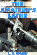
The Amateur's Lathe

"The Amateur's Lathe". A book in print since 1946, it assumes no prior knowledge and goes through all the basic and some advanced machining processes in a clear and logical way. Hence, it's an indispensable aid to the beginner - or even experienced turner. It includes such useful things as lathe design, the meaning of technical terms, names of lathe parts and how they relate to each other, how to choose a lathe, how to care for it, make adjustments, modifications and improvements. Included are details of how screwcutting and power feeds works and how to set up changewheels to provide a drive. Also included are charts for various pitches of leadscrew as commonly used on small lathes - one suitable for your lathe will certainly be amongst them. Various simple projects are also included with engineering drawings that allow some useful accessories to be made - rotating centre, 4-way toolpost, collet holder, tailstock threading die-holder, carriage length stop, etc. If you want to know about the fundamentals of lathe construction and use, how to set suitable turning speeds how to sharpen tools, set tool angles, read micrometers and verniers, etc.

Price: 
£12.75

Myford ML7 lathe First-ever 1947 Manual and Catalogue Set

Print code: 
MM535B

Myford ML7 Instruction and Maintenance Manual. Reproduction of the original 1946 version with the first-ever price list. Interesting, but scanty data. However, also included are copies of the first-ever Myford Catalogue - the very rare 16-page one marked "Preliminary" together with the first of the very detailed and well-illustrated 16-page ML7 Sales, Technical Specification and Accessories Catalogue. If you're as crazy about the ML7 as I am, this is the data set you need....

£35.00